


Rule of Thumbs for Structural Design


In this article, instead of discussing various formulas and earthquake code checks, we will talk about what we consider to be important points to pay attention to during the design phase, independently of calculations, from our engineering perspective.
Until the mid-17th century, the prevailing view was that larger structures could be built simply by scaling up smaller structural elements using proportion and similar load-bearing systems. However, this view was first rejected by Galileo because a crucial concept, "self-weight," posed a significant challenge to this approach. It became evident that due to their own weight (density), materials or elements had upper and lower limits in terms of providing economically viable solutions at certain scales. For example, while a truss system is the most suitable solution for bridge spans of 300-350 meters, for spans of 1500 meters, a completely different system, such as a cable suspension bridge, would be the appropriate choice. Over the years, based on various experiences, engineers have developed different types of structures and load-bearing systems for varying scales [1]. Below, number of stories commonly used in reinforced concrete load-bearing systems, as provided in Dr. S. Taranath’s book, are given as examples of these limits. The correct approach here is not to simply replicate these solutions but to utilize existing experience while addressing project-specific challenges optimally, and if necessary (as is often the nature of engineering), to propose innovative solutions. There is no need to rediscover America when utilizing existing knowledge. However, when we say "if necessary," growing populations may require taller structures, or geographic conditions may demand larger spans. In such cases, we must push the creative boundaries of engineering. On the other hand, if there is no geographic constraint and we choose the location with the maximum span for bridge construction or decide to invert the pyramid form, which has rested on a wide base for thousands of years, to support it on a single point (creating an inverted triangle), we must question our reasoning behind such choices.
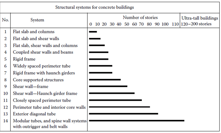
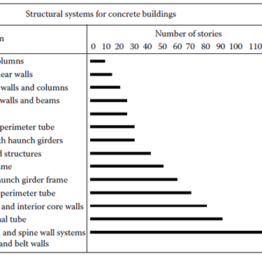
Şekil 1. Betonarme Taşıyıcı Sistemler
After a lengthy introduction, if we were to organize the design phase and our article under four main headings, we could group them as follows:
Crucial General Concepts (Strength, Rigidity, Ductility)
Preliminary Design and Coordination
Modeling, Calculation, and Interpretation [2]
Regulations [3]: Key Rules from the Informative Annex
1. Crucial General Concepts
Below, we have shared a slide presented by Prof. Dr. Alper during the Structural Strengthening Symposium in İzmir. According to this slide and engineering principles, if we fail to ensure sufficient strength, rigidity, and ductility in a structure, we can observe losses and reductions in the force-deformation graph of the structure. We must not forget that the capacities of our structural elements must be adequate—that is, they must have sufficient strength. If vertical load-bearing elements are subjected to service loads close to their capacity, this will eliminate their ability to deform while maintaining capacity, meaning they will not be ductile. Moreover, fundamental concepts, such as the importance of the building's rigidity in limiting displacements/drifts, must be kept in mind at every step of the design process.
Additionally, we should always be mindful of questions such as: Why do we divide the calculated forces by certain factors (R) and then multiply them by others (D)? What is the equal displacement rule? Understanding these concepts and being aware of why we do what we do is critical. Once again, let us emphasize: Strength, rigidity, and ductility are crucial.
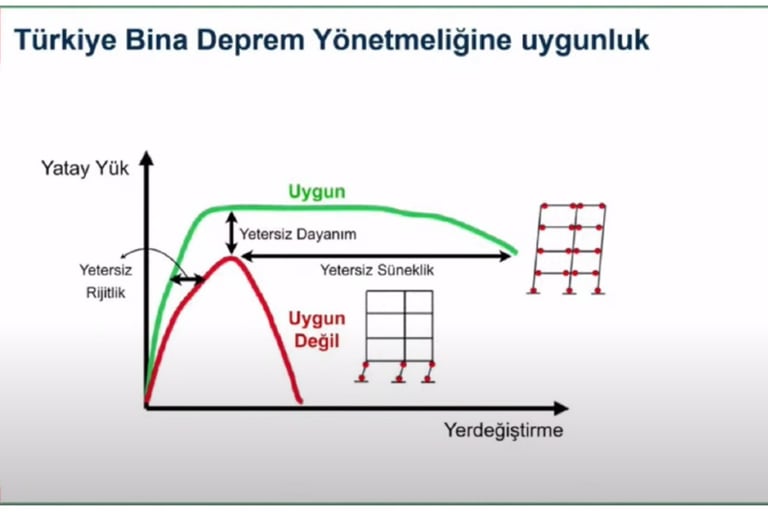
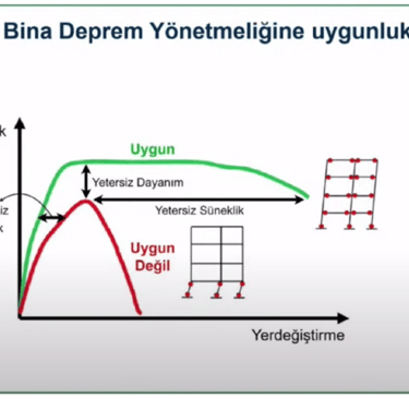
Şekil 2. Dayanım, Rijitlik, Süneklilik Kavramlarının Yapıdaki Etkisi [4]
2. Preliminary Design and Coordination
Firstly, we consider this section to be the most critical part of our article. Over time, the absence of civil engineers in every phase of design—especially during the initial steps when architectural concepts for residential projects are being created—has complicated subsequent stages of design. Preliminary architectural designs developed without considering civil engineering requirements make it difficult to establish an effective structural system. This issue can be resolved by ensuring that the architect and the civil engineer work in coordination from the very beginning. This approach allows for sufficient space to be allocated for vertical load-bearing elements, preventing the need for oversized structural sections that could affect the architectural design. Moreover, by creating a well-organized structural system both horizontally and vertically, a good load transfer can be achieved. Additionally, coordinated preliminary design prevents the emergence of undesirable or conceptually inconsistent engineering challenges later in the project.
3. Modeling, Calculation, and Interpretation
After preliminary sizing and the conceptual design phase, the steps of modeling the structural system with the help of a computer, performing calculations, and analyzing the results are carried out. Finally, drawings are prepared based on these evaluations. The topics of modeling, calculation, and interpretation are also discussed in Prof. Dr. G. H. Powell's book. Let us examine these topics from our own perspective.
Modeling
Using structural analysis software, we create an analytical model of the structure on the computer. One crucial point to remember during the modeling phase is that the model we create will never be an exact replica of the real structure, nor does it need to be. The model should be simple enough to represent the structure's behavior with sufficient accuracy. For instance, if an existing antenna on the structure appears in the mode shapes and influences the analysis results, it might be more appropriate to exclude it from the model. Additionally, by creating finer meshes in areas of irregular slab geometry and coarser meshes in regions with regular geometry, we can both reduce analysis time and accurately capture the desired force variations. Keeping analytical models as simple as possible will also help minimize the complexity involved in interpreting the results.
Calculation
The key point to emphasize under this heading is that software tools are just that—tools—and the results they produce must always be questioned. With advancing technology, nearly all calculations are performed using computer software. However, results can deviate from accuracy due to either internal errors in the software itself or user errors during the modeling phase. To be honest, many points that could be discussed under this heading are also applicable to the interpretation of results, making it difficult to draw a sharp distinction between the two. Nevertheless, the fundamental principle highlighted in the modeling section also applies here: we are analyzing an approximate model, and the results are only as accurate as the approximations allow. For instance, the decimal precision of force demands or a demand-to-capacity ratio of 1.0001 for a minor element in a structure with thousands of elements might seem critical at first glance. However, when you consider how the reinforcement arrangement (e.g., the switch between the first and second layer of reinforcement in a slab) can slightly increase or decrease this ratio, its insignificance becomes evident. What truly matters here is understanding the safety factors outlined in the regulations and being aware of how generally stressed the elements we design are. This awareness helps us focus on the bigger picture rather than overemphasizing minor numerical details.
Interpretation
Before starting to create drawings, the results obtained from the software should be roughly verified with manual calculations. Are the building periods logical? How close is the building weight value obtained from the program to the value calculated roughly by hand? Do the hand-calculated base shear values align with the program outputs? Questions like these will help identify any errors made in previous steps and increase our control over the design of the structure. After these necessary checks, the design can be finalized with the creation of the construction drawings.
4. Regulation Informative Annexes
The last of our main headings concerns the recommendations discussed in the informative annexes of the regulations. Although the annexes are not mandatory, they aim to help better understand and implement the regulations. The topics we will discuss here are crucial for achieving better practice.
Two points in the annexes focus on ensuring sufficient strength, rigidity, and ductility. All structural system adjustments required to achieve these are mandatory.
The structural system must be simple and straightforward. Due to modeling and element behavior uncertainties, as well as approximations in calculations, the design should not be made more complex. By keeping the system simple, we can avoid situations that we cannot fully account for in the calculations, resulting in a safer system design.
A regular and symmetric structural system ensures that inertial forces are transmitted evenly to the vertical load-bearing elements. Additionally, symmetry reduces the effects of extra eccentricities that may arise from differences in rigidity and mass centers. By avoiding sudden changes, we also minimize the risk of stress or load concentration in any part of the structure.
Honestly, the concepts and approaches we have mentioned in our article are fundamental issues that appear in most civil engineering textbooks and courses, and they are important considerations that may arise. Despite their fundamental nature, unfortunately, they are still either not fully understood or not given the necessary importance. For this reason, it will be beneficial for our community to continuously emphasize them.
References
[1] Taranath, B, S., Reinforced Concrete Design of Tall Buildings, New York. CRC Press, 2010.
[2] Powell, G, H., Modeling for Structural Analysis – Behavior and Basics, California. CSI, 2010.
[3] Türkiye Bina Deprem Yönetmeliği, Deprem Etkisi Altında Binaların Tasarımı için Kurallar, Afet ve Acil Durum Yönetimi Başkanlığı, Ankara, 2018.
[4] İlki, A., Yapılarda Güçlendirme Sempozyumu, Slayt 25, İzmir, 2023.